Get Started with Data Comms and the Raspberry Pi Pico
The Raspberry Pi Pico would be a great Internet of Things device but for one thing: it has no Internet connectivity. Fortunately, we can fix that with a Super SIM and an add-on cellular module such as Waveshare's Pico SIM7080.
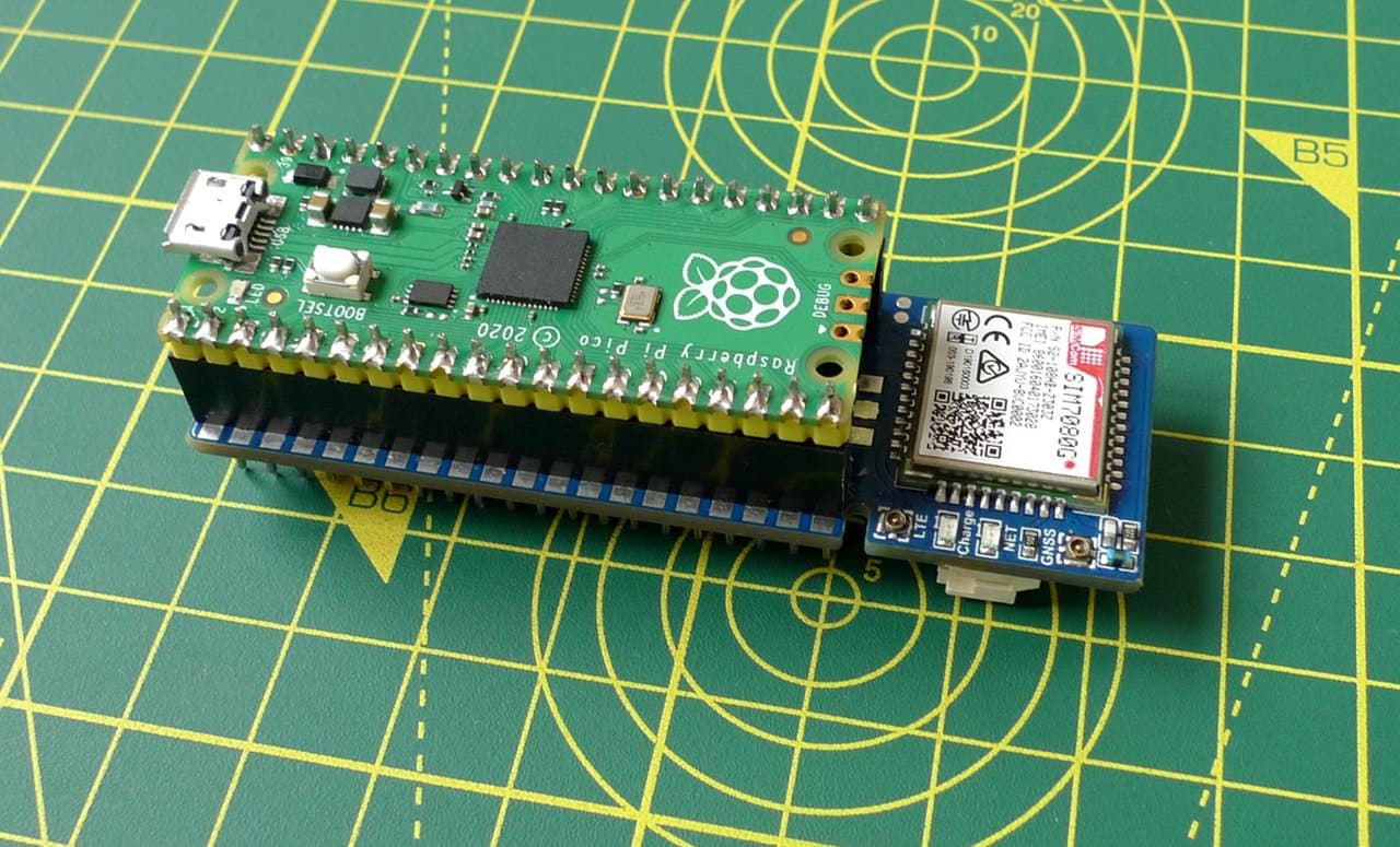
In our tutorial Get Started with SMS Commands and the Raspberry Pi Pico, we combined the Pico, the Waveshare Pico SIM7080 cellular module board, an MCP9808 temperature sensor, and a four-digit, seven-segment LED display into a prototype Internet of Things (IoT) development device.
This device uses Super SIM's SMS Commands API to receive commands over-the-air and, when instructed, to send back information. This works very well for device-to-user communications routed through your cloud, but what if you want the device to be able to reach out to other Internet resources? For that you need a data connection and the ability to make HTTP requests — GET, POST, PUT, etc. — and parse the remote server's response.
This tutorial will take you through the process of adding exactly this functionality to your IoT application.
Warning
This guide requires a Twilio account. Sign up here now if you don't have one. It also requires a configured Super SIM. If you haven't set up your Super SIM in the Console, please do so now. Our Super SIM First Steps guide has extra help if you need it.
If you have already completed Get Started with SMS Commands and the Raspberry Pi Pico, you're ready to jump straight to Step 2, below. If not, run through the SMS Commands tutorial's first four steps, which cover the crucial hardware and software setup that you will need to undertake in order to complete this tutorial.
Head there now and then come back here when you've completed Step 4.
Throughout this tutorial, you'll be pasting code from this page into a text editor, first the code below and then additional functions as you progress through the guide. At each stage, you'll copy the current code from your editor and paste it across to the Pico. The code included here entirely replaces hat from the previous tutorial in the series.
At this point, you should have a Pico with MicroPython installed. It should be fitted to the Waveshare board and connected to your computer by USB cable. You should have fired up Minicom (Mac/Linux) or PuTTY (Windows) and have the MicroPython REPL prompt, >>>. Hit Ctrl-C to exit the running program, if you don't see the prompt.
As a reminder, hit Ctrl-E to enter MicroPython's 'paste mode', paste in code copied from your text editor, and then hit Ctrl-D to start running it.
Alternatively, if you're a Mac or Linux user, you can use the pyboard.py tool to beam it over for you and relay the output to your terminal.
Here's the base code listing. Copy it — click on the copy icon in the top right corner of the listing; it'll appear as you mouse over the code — and paste it into your text editor.
Info
You can find the a complete listing of the code, including all subsequent additions, at our public GitHub repo.
Don't send it over to the Pico just yet — you'll need to complete Step 3 first.
1from machine import UART, Pin, I2C2from utime import ticks_ms, sleep3import json45class MCP9808:6"""7A simple driver for the I2C-connected MCP9808 temperature sensor.8This release supports MicroPython.9"""1011# *********** PRIVATE PROPERTIES **********1213i2c = None14address = 0x181516# *********** CONSTRUCTOR **********1718def __init__(self, i2c, i2c_address=0x18):19assert 0x00 <= i2c_address < 0x80, "ERROR - Invalid I2C address in MCP9808()"20self.i2c = i2c21self.address = i2c_address2223# *********** PUBLIC METHODS **********2425def read_temp(self):26# Read sensor and return its value in degrees celsius.27temp_bytes = self.i2c.readfrom_mem(self.address, 0x05, 2)28# Scale and convert to signed value.29temp_raw = (temp_bytes[0] << 8) | temp_bytes[1]30temp_cel = (temp_raw & 0x0FFF) / 16.031if temp_raw & 0x1000: temp_cel -= 256.032return temp_cel3334class HT16K33:35"""36A simple, generic driver for the I2C-connected Holtek HT16K33 controller chip.37This release supports MicroPython and CircuitPython3839Version: 3.0.240Bus: I2C41Author: Tony Smith (@smittytone)42License: MIT43Copyright: 202044"""4546# *********** CONSTANTS **********4748HT16K33_GENERIC_DISPLAY_ON = 0x8149HT16K33_GENERIC_DISPLAY_OFF = 0x8050HT16K33_GENERIC_SYSTEM_ON = 0x2151HT16K33_GENERIC_SYSTEM_OFF = 0x2052HT16K33_GENERIC_DISPLAY_ADDRESS = 0x0053HT16K33_GENERIC_CMD_BRIGHTNESS = 0xE054HT16K33_GENERIC_CMD_BLINK = 0x815556# *********** PRIVATE PROPERTIES **********5758i2c = None59address = 060brightness = 1561flash_rate = 06263# *********** CONSTRUCTOR **********6465def __init__(self, i2c, i2c_address):66assert 0x00 <= i2c_address < 0x80, "ERROR - Invalid I2C address in HT16K33()"67self.i2c = i2c68self.address = i2c_address69self.power_on()7071# *********** PUBLIC METHODS **********7273def set_blink_rate(self, rate=0):74"""75Set the display's flash rate.76"""77assert rate in (0, 0.5, 1, 2), "ERROR - Invalid blink rate set in set_blink_rate()"78self.blink_rate = rate & 0x0379self._write_cmd(self.HT16K33_GENERIC_CMD_BLINK | rate << 1)8081def set_brightness(self, brightness=15):82"""83Set the display's brightness (ie. duty cycle).84"""85if brightness < 0 or brightness > 15: brightness = 1586self.brightness = brightness87self._write_cmd(self.HT16K33_GENERIC_CMD_BRIGHTNESS | brightness)8889def draw(self):90"""91Writes the current display buffer to the display itself.92"""93self._render()9495def update(self):96"""97Alternative for draw() for backwards compatibility98"""99self._render()100101def clear(self):102"""103Clear the buffer.104"""105for i in range(0, len(self.buffer)): self.buffer[i] = 0x00106return self107108def power_on(self):109"""110Power on the controller and display.111"""112self._write_cmd(self.HT16K33_GENERIC_SYSTEM_ON)113self._write_cmd(self.HT16K33_GENERIC_DISPLAY_ON)114115def power_off(self):116"""117Power on the controller and display.118"""119self._write_cmd(self.HT16K33_GENERIC_DISPLAY_OFF)120self._write_cmd(self.HT16K33_GENERIC_SYSTEM_OFF)121122# ********** PRIVATE METHODS **********123124def _render(self):125"""126Write the display buffer out to I2C127"""128buffer = bytearray(len(self.buffer) + 1)129buffer[1:] = self.buffer130buffer[0] = 0x00131self.i2c.writeto(self.address, bytes(buffer))132133def _write_cmd(self, byte):134"""135Writes a single command to the HT16K33. A private method.136"""137self.i2c.writeto(self.address, bytes([byte]))138139class HT16K33Segment(HT16K33):140"""141Micro/Circuit Python class for the Adafruit 0.56-in 4-digit,1427-segment LED matrix backpack and equivalent Featherwing.143144Version: 3.0.2145Bus: I2C146Author: Tony Smith (@smittytone)147License: MIT148Copyright: 2020149"""150151# *********** CONSTANTS **********152153HT16K33_SEGMENT_COLON_ROW = 0x04154HT16K33_SEGMENT_MINUS_CHAR = 0x10155HT16K33_SEGMENT_DEGREE_CHAR = 0x11156HT16K33_SEGMENT_SPACE_CHAR = 0x00157158# The positions of the segments within the buffer159POS = (0, 2, 6, 8)160161# Bytearray of the key alphanumeric characters we can show:162# 0-9, A-F, minus, degree163CHARSET = b'\x3F\x06\x5B\x4F\x66\x6D\x7D\x07\x7F\x6F\x5F\x7C\x58\x5E\x7B\x71\x40\x63'164165# *********** CONSTRUCTOR **********166167def __init__(self, i2c, i2c_address=0x70):168self.buffer = bytearray(16)169super(HT16K33Segment, self).__init__(i2c, i2c_address)170171# *********** PUBLIC METHODS **********172173def set_colon(self, is_set=True):174"""175Set or unset the display's central colon symbol.176"""177self.buffer[self.HT16K33_SEGMENT_COLON_ROW] = 0x02 if is_set is True else 0x00178return self179180def set_glyph(self, glyph, digit=0, has_dot=False):181"""182Present a user-defined character glyph at the specified digit.183"""184assert 0 <= digit < 4, "ERROR - Invalid digit (0-3) set in set_glyph()"185assert 0 <= glyph < 0xFF, "ERROR - Invalid glyph (0x00-0xFF) set in set_glyph()"186self.buffer[self.POS[digit]] = glyph187if has_dot is True: self.buffer[self.POS[digit]] |= 0x80188return self189190def set_number(self, number, digit=0, has_dot=False):191"""192Present single decimal value (0-9) at the specified digit.193"""194assert 0 <= digit < 4, "ERROR - Invalid digit (0-3) set in set_number()"195assert 0 <= number < 10, "ERROR - Invalid value (0-9) set in set_number()"196return self.set_character(str(number), digit, has_dot)197198def set_character(self, char, digit=0, has_dot=False):199"""200Present single alphanumeric character at the specified digit.201"""202assert 0 <= digit < 4, "ERROR - Invalid digit set in set_character()"203char = char.lower()204char_val = 0xFF205if char == "deg":206char_val = HT16K33_SEGMENT_DEGREE_CHAR207elif char == '-':208char_val = self.HT16K33_SEGMENT_MINUS_CHAR209elif char == ' ':210char_val = self.HT16K33_SEGMENT_SPACE_CHAR211elif char in 'abcdef':212char_val = ord(char) - 87213elif char in '0123456789':214char_val = ord(char) - 48215assert char_val != 0xFF, "ERROR - Invalid char string set in set_character()"216self.buffer[self.POS[digit]] = self.CHARSET[char_val]217if has_dot is True: self.buffer[self.POS[digit]] |= 0x80218return self219220'''221Send an AT command - return True if we got an expected222response ('back'), otherwise False223'''224def send_at(cmd, back="OK", timeout=1000):225# Send the command and get the response (until timeout)226buffer = send_at_get_resp(cmd, timeout)227if len(buffer) > 0: return (back in buffer)228return False229230'''231Send an AT command - just return the response232'''233def send_at_get_resp(cmd, timeout=1000):234# Send the AT command235modem.write((cmd + "\r\n").encode())236237# Read and return the response (until timeout)238return read_buffer(timeout)239240'''241Read in the buffer by sampling the UART until timeout242'''243def read_buffer(timeout):244buffer = bytes()245now = ticks_ms()246while (ticks_ms() - now) < timeout and len(buffer) < 1025:247if modem.any():248buffer += modem.read(1)249return buffer.decode()250251'''252Module startup detection253Send a command to see if the modem is powered up254'''255def boot_modem():256state = False257count = 0258while count < 20:259if send_at("ATE1"):260print("The modem is ready")261return True262if not state:263print("Powering the modem")264module_power()265state = True266sleep(4)267count += 1268return False269270'''271Power the module on/off272'''273def module_power():274pwr_key = Pin(14, Pin.OUT)275pwr_key.value(1)276sleep(1.5)277pwr_key.value(0)278279'''280Check we are attached281'''282def check_network():283is_connected = False284response = send_at_get_resp("AT+COPS?")285line = split_msg(response, 1)286if "+COPS:" in line:287is_connected = (line.find(",") != -1)288if is_connected: print("Network information:", line)289return is_connected290291'''292Configure the modem293'''294def configure_modem():295# NOTE AT commands can be sent together, not one at a time.296# Set the error reporting level, set SMS text mode, delete left-over SMS297# select LTE-only mode, select Cat-M only mode, set the APN to 'super' for Super SIM298send_at("AT+CMEE=2;+CMGF=1;+CMGD=,4;+CNMP=38;+CMNB=1;+CGDCONT=1,\"IP\",\"super\"")299# Set SSL version, SSL no verify, set HTTPS request parameters300send_at("AT+CSSLCFG=\"sslversion\",1,3;+SHSSL=1,\"\";+SHCONF=\"BODYLEN\",1024;+SHCONF=\"HEADERLEN\",350")301print("Modem configured for Cat-M and Super SIM")302303'''304Open/close a data connection to the server305'''306def open_data_conn():307# Activate a data connection using PDP 0,308# but first check it's not already open309response = send_at_get_resp("AT+CNACT?")310line = split_msg(response, 1)311status = get_field_value(line, 1)312313if status == "0":314# Inactive data connection so start one up315success = send_at("AT+CNACT=0,1", "ACTIVE", 2000)316elif status in ("1", "2"):317# Active or operating data connection318success = True319320print("Data connection", "active" if success else "inactive")321return success322323def close_data_conn():324# Just close the connection down325send_at("AT+CNACT=0,0")326print("Data connection inactive")327328'''329Start/end an HTTP session330'''331def start_session(server):332# Deal with an existing session if there is one333if send_at("AT+SHSTATE?", "1"):334print("Closing existing HTTP session")335send_at("AT+SHDISC")336337# Configure a session with the server...338send_at("AT+SHCONF=\"URL\",\"" + server + "\"")339340# ...and open it341resp = send_at_get_resp("AT+SHCONN", 2000)342# The above command may take a while to return, so343# continue to check the UART until we have a response,344# or 90s passes (timeout)345now = ticks_ms()346while ((ticks_ms() - now) < 90000):347#if len(resp) > 0: print(resp)348if "OK" in resp: return True349if "ERROR" in resp: return False350resp = read_buffer(1000)351return False352353def end_session():354# Break the link to the server355send_at("AT+SHDISC")356print("HTTP session closed")357358'''359Set a standard request header360'''361def set_request_header():362global req_head_set363364# Check state variable to see if we need to365# set the standard request header366if not req_head_set:367send_at("AT+SHCHEAD")368send_at("AT+SHAHEAD=\"Content-Type\",\"application/x-www-form-urlencoded\";+SHAHEAD=\"User-Agent\",\"twilio-pi-pico/1.0.0\"")369send_at("AT+SHAHEAD=\"Cache-control\",\"no-cache\";+SHAHEAD=\"Connection\",\"keep-alive\";+SHAHEAD=\"Accept\",\"*/*\"")370req_head_set = True371372'''373Make a request to the specified server374'''375def issue_request(server, path, body, verb):376result = ""377378# Check the request verb379code = 0380verbs = ["GET", "PUT", "POST", "PATCH", "HEAD"]381if verb.upper() in verbs:382code = verbs.index(verb) + 1383else:384print("ERROR -- Unknown request verb specified")385return ""386387# Attempt to open a data session388if start_session(server):389print("HTTP session open")390# Issue the request...391set_request_header()392print("HTTP request verb code:",code)393if body != None: set_request_body(body)394response = send_at_get_resp("AT+SHREQ=\"" + path + "\"," + str(code))395start = ticks_ms()396while ((ticks_ms() - start) < 90000):397if "+SHREQ:" in response: break398response = read_buffer(1000)399400# ...and process the response401lines = split_msg(response)402for line in lines:403if len(line) == 0: continue404if "+SHREQ:" in line:405status_code = get_field_value(line, 1)406if int(status_code) > 299:407print("ERROR -- HTTP status code",status_code)408break409410# Get the data from the modem411data_length = get_field_value(line, 2)412if data_length == "0": break413response = send_at_get_resp("AT+SHREAD=0," + data_length)414415# The JSON data may be multi-line so store everything in the416# response that comes after (and including) the first '{'417pos = response.find("{")418if pos != -1: result = response[pos:]419end_session()420else:421print("ERROR -- Could not connect to server")422return result423424'''425Flash the Pico LED426'''427def led_blink(blinks):428for i in range(0, blinks):429led_off()430sleep(0.25)431led_on()432sleep(0.25)433434def led_on():435led.value(1)436437def led_off():438led.value(0)439440'''441Split a response from the modem into separate lines,442removing empty lines and returning all that's left or,443if 'want_line' has a non-default value, return that one line444'''445def split_msg(msg, want_line=99):446lines = msg.split("\r\n")447results = []448for i in range(0, len(lines)):449if i == want_line:450return lines[i]451if len(lines[i]) > 0:452results.append(lines[i])453return results454455'''456Extract the SMS index from a modem response line457'''458def get_sms_number(line):459return get_field_value(line, 1)460461'''462Extract a comma-separated field value from a line463'''464def get_field_value(line, field_num):465parts = line.split(",")466if len(parts) > field_num:467return parts[field_num]468return ""469470'''471Blink the LED n times after extracting n from the command string472'''473def process_command_led(msg):474blinks = msg[4:]475print("Blinking LED",blinks,"time(s)")476try:477led_blink(int(blinks))478except:479print("BAD COMMAND:",blinks)480481'''482Display the decimal value n after extracting n from the command string483'''484def process_command_num(msg):485value = msg[4:]486print("Setting",value,"on the LED")487try:488# Extract the decimal value (string) from 'msg' and convert489# to a hex integer for easy presentation of decimal digits490hex_value = int(value, 16)491display.set_number((hex_value & 0xF000) >> 12, 0)492display.set_number((hex_value & 0x0F00) >> 8, 1)493display.set_number((hex_value & 0x00F0) >> 4, 2)494display.set_number((hex_value & 0x000F), 3).update()495except:496print("BAD COMMAND:",value)497498'''499Get a temperature reading and send it back as an SMS500'''501def process_command_tmp():502print("Sending a temperature reading")503celsius_temp = "{:.2f}".format(sensor.read_temp())504if send_at("AT+CMGS=\"000\"", ">"):505# '>' is the prompt sent by the modem to signal that506# it's waiting to receive the message text.507# 'chr(26)' is the code for ctrl-z, which the modem508# uses as an end-of-message marker509r = send_at_get_resp(celsius_temp + chr(26))510511'''512Make a request to a sample server513'''514def process_command_get():515print("Requesting data...")516server = "YOUR_BEECEPTOR_URL"517endpoint_path = "/api/v1/status"518519# Attempt to open a data connection520if open_data_conn():521result = issue_request(server, endpoint_path, None, "GET")522if len(result) > 0:523# Decode the received JSON524try:525response = json.loads(result)526# Extract an integer value and show it on the display527if "status" in response:528process_command_num("NUM=" + str(response["status"]))529except:530print("ERROR -- No JSON data received. Raw:\n",result)531else:532print("ERROR -- No JSON data received")533534# Close the open connection535close_data_conn()536537'''538Listen for incoming SMS Commands539'''540def listen():541print("Listening for Commands...")542while True:543# Did we receive a Unsolicited Response Code (URC)?544buffer = read_buffer(5000)545if len(buffer) > 0:546lines = split_msg(buffer)547for line in lines:548if "+CMTI:" in line:549# We received an SMS, so get it...550num = get_sms_number(line)551msg = send_at_get_resp("AT+CMGR=" + num, 2000)552553# ...and process it for commands554cmd = split_msg(msg, 2).upper()555if cmd.startswith("LED="):556process_command_led(cmd)557elif cmd.startswith("NUM="):558process_command_num(cmd)559elif cmd.startswith("TMP"):560process_command_tmp()561elif cmd.startswith("GET"):562process_command_get()563else:564print("UNKNOWN COMMAND:",cmd)565# Delete all SMS now we're done with them566send_at("AT+CMGD=,4")567568# Globals569req_head_set = False570571# Set up the modem UART572modem = UART(0, 115200)573574# Set up I2C and the display575i2c = I2C(1, scl=Pin(3), sda=Pin(2))576display = HT16K33Segment(i2c)577display.set_brightness(2)578display.clear().draw()579580# Set up the MCP9808 sensor581sensor = MCP9808(i2c=i2c)582583# Set the LED and turn it off584led = Pin(25, Pin.OUT)585led_off()586587# Start the modem588if boot_modem():589configure_modem()590591# Check we're attached592state = True593while not check_network():594if state:595led_on()596else:597led_off()598state = not state599600# Light the LED601led_on()602603# Begin listening for commands604listen()605else:606# Error! Blink LED 5 times607led_blink(5)608led_off()
This is the basis of the code you'll work on through the remainder of the guide. What does it do? Much of it is the code you worked on last time, so let's focus on the additions.
To communicate with Internet resources, the modem needs to establish a data connection through the cellular network, and then an HTTP connection to the target server. Lastly, it creates and sends an HTTP request to that server, and reads back the response.
The function open_data_conn() handles the first part, by sending the AT command CNACT=0,1. The 0 is the 'Packet Data Protocol (PDP) context', essentially one of a number of IP channels the modem provides. The 1 is the instruction to enable the data connection.
When the data connection is up, the code calls start_session() to open an HTTP connection to a specific server, which is passed in as an argument. The server is set using AT+SHCONF="URL","<SERVER_DOMAIN>" and the connection then opened with AT+SHCONN.
Requests are made through the function issue_request(). It calls start_session() and then sets up the request: we build the header on the modem (and keep it for future use) and then send AT+SHREQ= with the path to a resource and the value 1 as parameters — the 1 indicates it is a GET request.
The response returned by the modem contains information about the data returned by the server, which is stored on the modem. The code uses this information to get the HTTP status code — to check the request was successful — and the response's length. If the latter is non-zero, the code sends AT+SHREAD= to retrieve that many bytes from the modem's cache. issue_request() extracts any JSON in the response and returns it.
All this is triggered by the receipt of an SMS command, GET, which causes the function process_command_get() to be called. This function calls open_data_conn() and then issue_request(). It parses the received data as JSON and displays the value of a certain field on the LED display using code you worked on in the previous tutorial.
Info
When the code runs, it turns off the Pico's built-in LED. The LED will flash rapidly five times if there was a problem booting the modem.
The LED is turned on when the device is attached to the network. If the LED is flashing slowly, that means it has not yet attached. Please be patient; it will attach shortly.
Before you can run the code, you need to set up the data that will be retrieved. You're going to use Beeceptor as a proxy for the Internet resource your IoT device will be communicating with. In a real-world application, you would sign up to use a specific service and access that, but Beeceptor makes a very handy stand-in. Let's set it up to receive HTTP GET requests from the device.
-
In a web browser tab, go to Beeceptor.
-
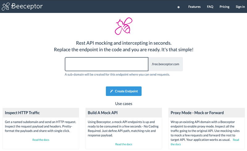
Enter an endpoint name in the large text field and click Create Endpoint:
-
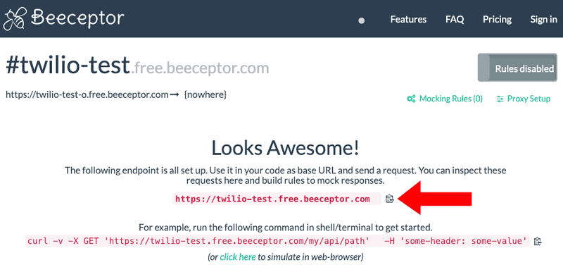
On the screen that appears next, click on the upper of the two clipboard icons to copy the endpoint URL:
-
Keep the tab open.
-
Jump back to your text editor and locate the
process_command_get()function in the Python code. Paste the endpoint URL you got from step 3, in place ofYOUR_BEECEPTOR_URL. -
Save the file and then transfer it over to the Pico.
-
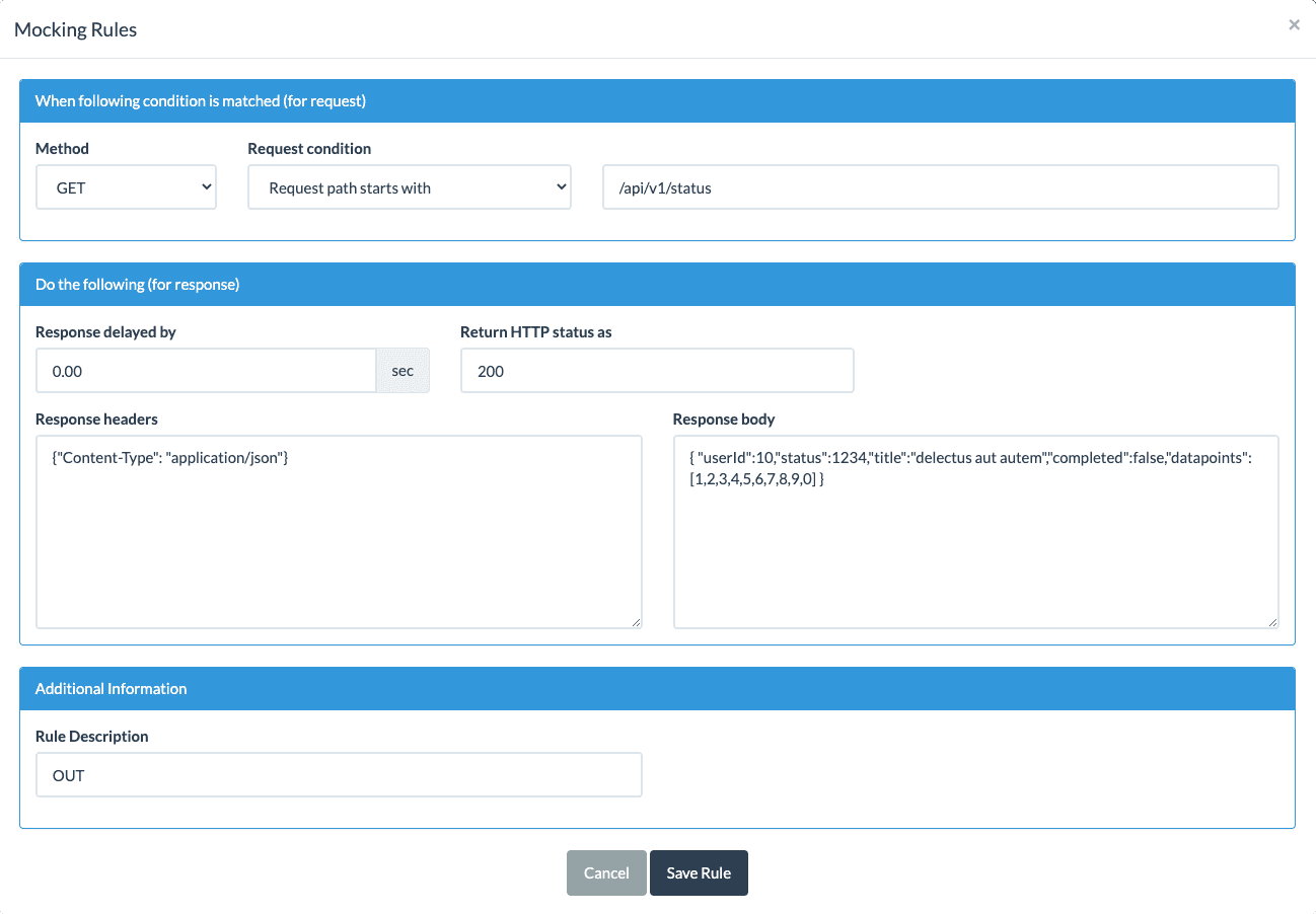
Hop back to Beeceptor and click on Mocking Rules (0) in the page shown above and then click Create New Rule.
-
In the third field, add
api/v1/statusright after the/that's already there. -
Under Response Body, paste the following JSON, your test API's sample output:
{ "userId":10,"status":1234,"title":"delectus aut autem","completed":false,"datapoints":[1,2,3,4,5,6,7,8,9,0] } -
The panel should look like this:
-
Click Save Rule and then close the Mocking Rules panel by clicking the X in the top right corner.
-
Again, keep the tab open.
Switch over to Minicom (or PuTTY). When you see the Listening for commands... message, open a separate terminal tab or window and enter the following command:
1twilio api:supersim:v1:sms-commands:create \2--sim "<YOUR_SIM_NAME_OR_SID>" \3--payload GET
You'll need to replace the sections in angle brackets (< and >) with your own information, just as you did last time. Your SIM's SID — or friendly name if you've set one — and the specified account credentials are all accessible from the Twilio Console.
This command uses the Super SIM API's SMS Commands API to send a machine-to-machine message to the Pico. The --payload parameter tells Twilio what the body of the SMS should be: it's whatever comes after the equals sign. In this case, that's GET, the command to which we want the Pico to respond.
The listen() function in your Python code keeps an ear open for incoming SMS messages, which are signalled by the module transmitting a string that includes the characters +CMTI:. If it appears, the code sends a new AT command to the modem to get the message (AT+CMGR) and then awaits a response. When the response comes, the code processes it and extracts the GET — which tells the device to make an HTTP request of that type.
You'll see all this in your terminal window:
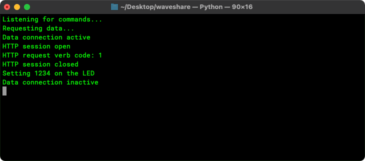
You should also see 1234 displayed on the LED — one part of the data received from the API you connected to!
Info
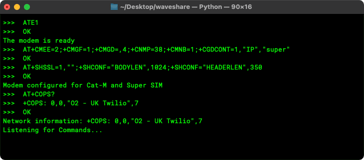
The code listed above will output state messages, but if you want to see the full flow of AT command requests and their responses, you'll need to add a handful of extra lines. To do so, drop in this function:
1'''2Output raw data3'''4def debug_output(msg):5for line in split_msg(msg): print(">>> ",line)
and add this line right before the final return in the function read_buffer():
debug_output(buffer.decode())
The output will now look like this:
Reaching out across the Internet and requesting information is only half of the story: you also want to push data out to the cloud. Our Pico-based IoT demo is well prepared to be a source of information: it includes a temperature sensor which you can read and transmit the result by SMS if you send the command TMP by text message.
Not all data receivers accept input by SMS, however. Most will accept POST requests, though, so let's add the code to the application to support that. There are a number of changes and additions to make.
Add the following code right below the def set_request_header(): function definition:
1'''2Set request body3'''4def set_request_body(body):5send_at("AT+SHCPARA;+SHPARA=\"data\",\"" + body + "\"")67'''8Make a GET, POST requests to the specified server9'''10def get_data(server, path):11return issue_request(server, path, None, "GET")1213def send_data(server, path, data):14return issue_request(server, path, data, "POST")
Replace the existing issue_request() function with this code:
1def issue_request(server, path, body, verb):2result = ""34# Check the request verb5code = 06verbs = ["GET", "PUT", "POST", "PATCH", "HEAD"]7if verb.upper() in verbs:8code = verbs.index(verb) + 19else:10print("ERROR -- Unknown request verb specified")11return ""1213# Attempt to open a data session14if start_session(server):15print("HTTP session open")16# Issue the request...17set_request_header()18print("HTTP request verb code:",code)19if body != None: set_request_body(body)20response = send_at_get_resp("AT+SHREQ=\"" + path + "\"," + str(code))21start = ticks_ms()22while ((ticks_ms() - start) < 90000):23if "+SHREQ:" in response: break24response = read_buffer(1000)2526# ...and process the response27lines = split_msg(response)28for line in lines:29if len(line) == 0: continue30if "+SHREQ:" in line:31status_code = get_field_value(line, 1)32if int(status_code) > 299:33print("ERROR -- HTTP status code",status_code)34break3536# Get the data from the modem37data_length = get_field_value(line, 2)38if data_length == "0": break39response = send_at_get_resp("AT+SHREAD=0," + data_length)4041# The JSON data may be multi-line so store everything in the42# response that comes after (and including) the first '{'43pos = response.find("{")44if pos != -1: result = response[pos:]45end_session()46else:47print("ERROR -- Could not connect to server")48return result
Replace the process_command_get() function with all of the following code:
1'''2Make a request to a sample server3'''4def process_command_get():5print("Requesting data...")6server = "YOUR_BEECEPTOR_URL"7endpoint_path = "/api/v1/status"8process_request(server, endpoint_path)910def process_command_post():11print("Sending data...")12server = "YOUR_BEECEPTOR_URL"13endpoint_path = "/api/v1/logs"14process_request(server, endpoint_path, "{:.2f}".format(sensor.read_temp()))1516def process_request(server, path, data=None):17# Attempt to open a data connection18if open_data_conn():19if data is not None:20result = send_data(server, path, data)21else:22result = get_data(server, path)2324if len(result) > 0:25# Decode the received JSON26try:27response = json.loads(result)28# Extract an integer value and show it on the display29if "status" in response:30process_command_num("NUM=" + str(response["status"]))31except:32print("ERROR -- No JSON data received. Raw:\n",result)33else:34print("ERROR -- No JSON data received")3536# Close the open connection37close_data_conn()
When you've done that, copy and paste your Beeceptor endpoint URL into the places marked YOUR_BEECEPTOR_URL.
Finally, add the following lines to the listen() function, right below the code that looks for a GET command:
1elif cmd.startswith("POST"):2process_command_post()
Finally, transfer the updated program to the Pico.
You can't send data without somewhere to post it, so set that up now. Once more, Beeceptor comes to our assistance: you're going to add a mocking rule as a stand-in for an application server that will take in the data the device posts and return a status message.
-
Switch to the web browser tab showing Beeceptor.
-
Click on Mocking Rules (1) and then Create New Rule.
-
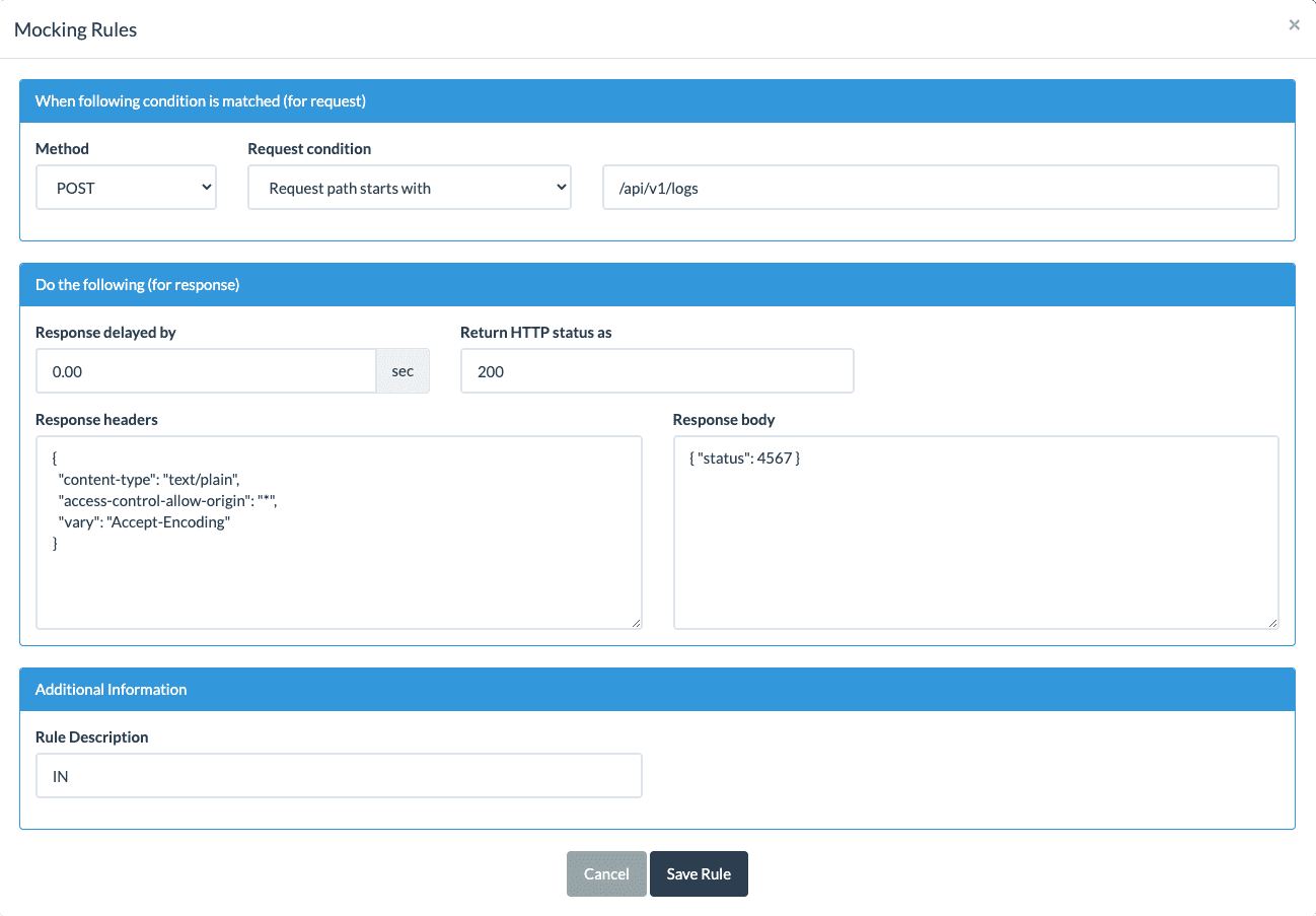
Under Method, select
POST. -
In the third field, add
api/v1/logsright after the/that's already there. -
Under Response Body, paste the following JSON:
{ "status":4567 } -
The panel should look like this:
-
Click Save Rule and then close the Mocking Rules panel by clicking the X in the top right corner.
-
Again, keep the tab open.
Switch over to Minicom (or PuTTY). When you see the Listening for commands... message, open a separate terminal tab or window and enter the following command, filling in your details where necessary:
1twilio api:supersim:v1:sms-commands:create \2--sim "<YOUR_SIM_NAME_OR_SID>" \3--payload POST
This time, you'll see all this in your terminal window:
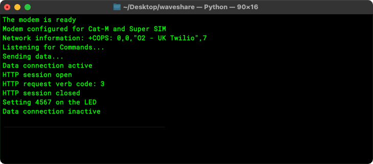
You should also see 4567 displayed on the LED — one part of the data received bacl from the API. Speaking of the API, what did it see? Take a look at Beeceptor. It records the receipt of a POST request to /api/v1/logs, and if you click on the entry in the table, then the JSON icon ({:}) above the Request body panel, you'll see the celsius temperature as received data:

You now have a Raspberry Pi Pico-based IoT device that can send and receive data across the Internet. In this demo, you've used test APIs for getting and posting data, and triggered both by manually sending an SMS command. Why not adapt the code not only to make use of different APIs — perhaps one you might make use of in your production IoT device — but also to do so automatically, at a time appropriate to the application? For example, you might include a regular weather forecast update, or pull in the output from a Slack channel. You might post device status data to your own cloud.
Wherever you take your Raspberry Pi Pico-based IoT device next, we can't wait to see what you build!
When this was written, of course: the Pico W has been release since then. Back to top